Separate IoT and Guest Networks with VLANs
Smart plugs, cameras and guests' phones do not need to see your laptop or NAS. VLANs split one physical network into several isolated ones that share the same cables, switch and access points.
The plan
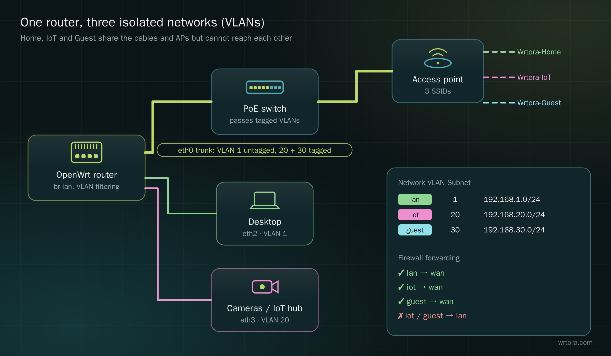
| lan | VLAN 1, 192.168.1.0/24 — your own devices |
|---|---|
| iot | VLAN 20, 192.168.20.0/24 — cameras, plugs, TVs; internet only |
| guest | VLAN 30, 192.168.30.0/24 — visitors; internet only |
| eth0 | Trunk to the switch and APs: VLAN 1 untagged, 20 and 30 tagged |
| eth2 / eth3 | Access ports: eth2 in VLAN 1 (desktop), eth3 in VLAN 20 (IoT hub) |
1. Bridge VLAN filtering
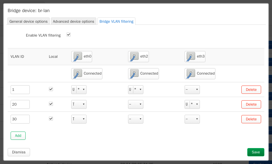
Network → Interfaces → Devices → br-lan → Configure… → Bridge VLAN filtering. Tick Enable VLAN filtering and add one row per VLAN. U = untagged, T = tagged, * = the port's native VLAN.
2. One interface per VLAN
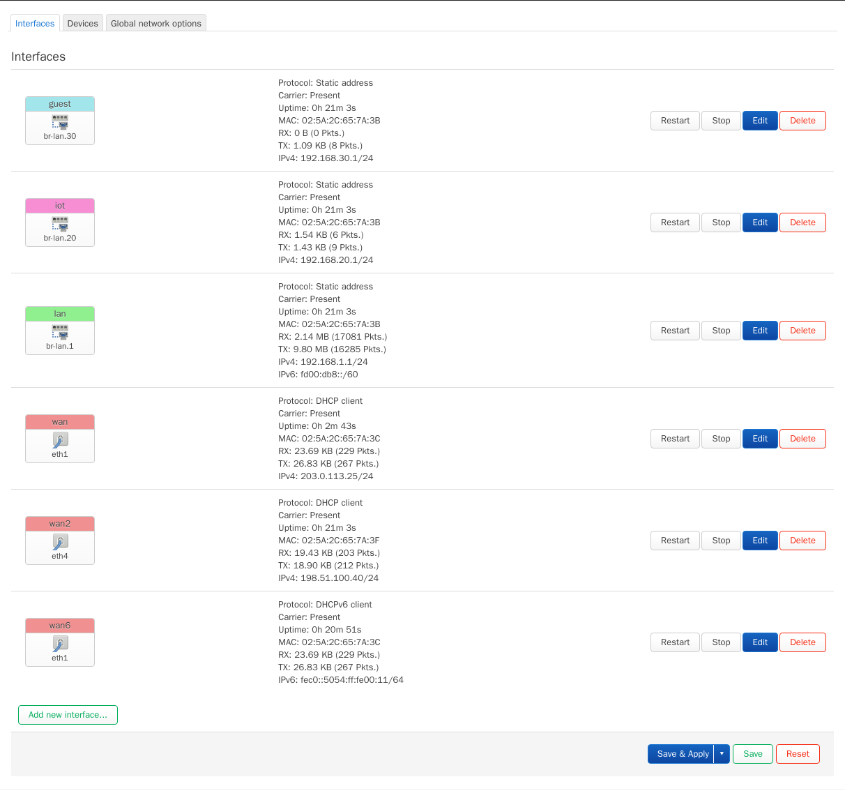
- Edit lan and set its Device to br-lan.1
- Add new interface iot: protocol Static address, device br-lan.20, address 192.168.20.1/24, and enable the DHCP server
- Add guest the same way on br-lan.30 with 192.168.30.1/24
3. Firewall zones
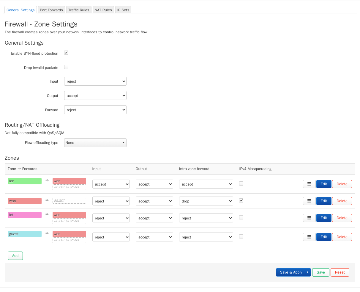
Network → Firewall: create zones iot and guest with Input reject and Forward reject, and allow forwarding only to wan. Then add two traffic rules that accept DHCP and DNS (UDP/TCP ports 53 and 67) from each zone to the router.
4. One SSID per network
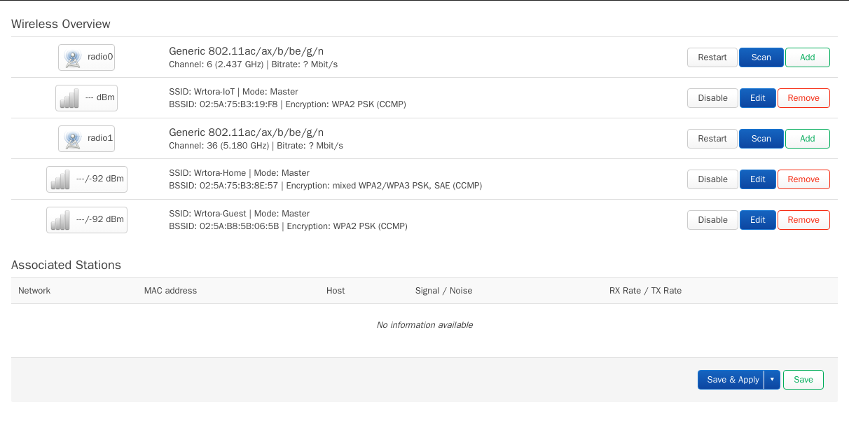
Under Network → Wireless, attach Wrtora-IoT to iot and Wrtora-Guest to guest (tick Isolate Clients on guest). On separate access points, create the same VLANs on the AP's own bridge and attach each SSID to its VLAN.
Check it works
- A phone on Wrtora-Guest gets a 192.168.30.x address and can browse the web
- From that phone, 192.168.1.1 and your NAS do not answer
- The switch between router and APs must pass tagged VLANs: a managed switch such as the Wrtora S8M or the SP8 PoE